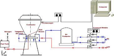
In current scenario, environmental pollution has become a greater challenge for the whole mankind. Main source of the pollutant includes industrial applications, air and land based traffic. These emissions are mainly CO, NO x and UHC (unburned hydro carbon) causing many harmful effects like acid rain, smog and haze resulting in global warming. It is expected that emissions norms will become stricter in near future. It is reported that by 2025, NO x , CO and UHC should be reduced by 80%. To address these challenges, we are trying to develop a newer combustion device in our Combustion Research Laboratory, IIT Bombay.MILD / flameless combustion has been reported to have several promising features of very low CO and NO x emissions. Flameless combustion of liquid fuels has been investigated by our research group. Our aim is to reduce the chemical as well as acoustic emissions to a great extent. Internal exhaust gas recirculation is one of the key parameter to achieve flameless combustion in our ongoing investigation. We are using a conical combustor geometry along with a chamfered plate at the top of the combustor to achieve the optimum exhaust gas recirculation. Tangential air injection is being used for the enhanced mixing between fuel and oxidiser. The combustor is tested up to a thermal input of ~54 kW (energy density ~13.5 MW/m 3 ) while operating in flameless mode. Land based (stationary) and air based (moving) gas turbine engines operate in high energy density window, hence this new design aims at the possible application in aircrafts and gas turbine power plant combustors. Several fuels such as liquid
kerosene, diesel, and biodiesel are being investigated in our laboratory. Measured CO, NO x , and sound level emissions are less than 10 ppm and 97 dB in flameless mode for a thermal input of 30 kW as shown in Fig. 2 and 3.
Prof. Sudarshan Kumar
