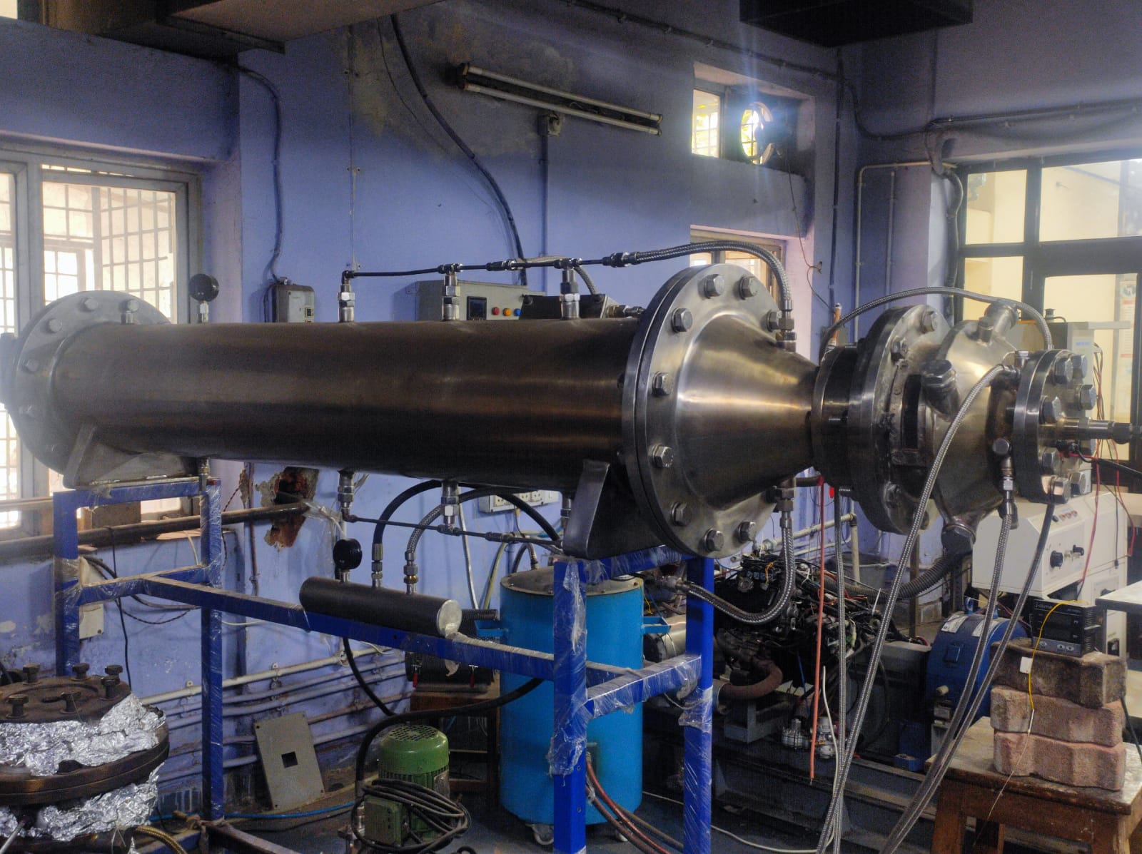
In a world highly dependent upon combustion-derived energy, it is essential to develop technology that can address various problems associated with combustion energy, such as air and noise pollution, while at the same time maintaining energy efficiency and other performance markers. This invention relates to a unique air injection scheme in a conventional swirl-stabilized combustion chamber with a combustion mode, which results in a no visible flame also known as flameless combustion and a significant reduction in CO, NOx and acoustic emissions, while dealing with the issues of the same through the design.
- A unique air injection scheme in a conventional swirl-stabilized combustion chamber with a combustion mode, which results in a no visible flame also known as flameless combustion even for very lean fuel-air mixtures
- Strong swirl and high recirculation environment for operating conditions similar to gas turbines.
- It is composed of three different sections namely, primary zone, secondary zone, and dilution zone.
- It consists of a liner with appropriate arrangements for air supply into the combustion chamber, an air swirler, fuel supply unit with an atomizer, and jackets. Jackets are welded as an outer envelope to ensure proper air flow distribution inside the combustor.
- Air flow inside the combustor from primary and secondary holes creates a clockwise reverse flow swirl while seeing from the top. The primary and secondary air injection in reverse direction assisted with the injection of dilution air results in increased mixing of the hot combustion products with fresh reactants
Demonstration and/or validation in lab environment (TRL 4)
4
This combustor enables a reduction in pollutant emission and noise production during its operation, while not compromising on energy efficiency. This is particularly important given the dependence of the global economy on combustion based energy, and the problems of global warming and climate change which require urgent attention.
This combustor can be used in gas turbine engines, which in turn have a multitude of applications.
201921023135
503550

