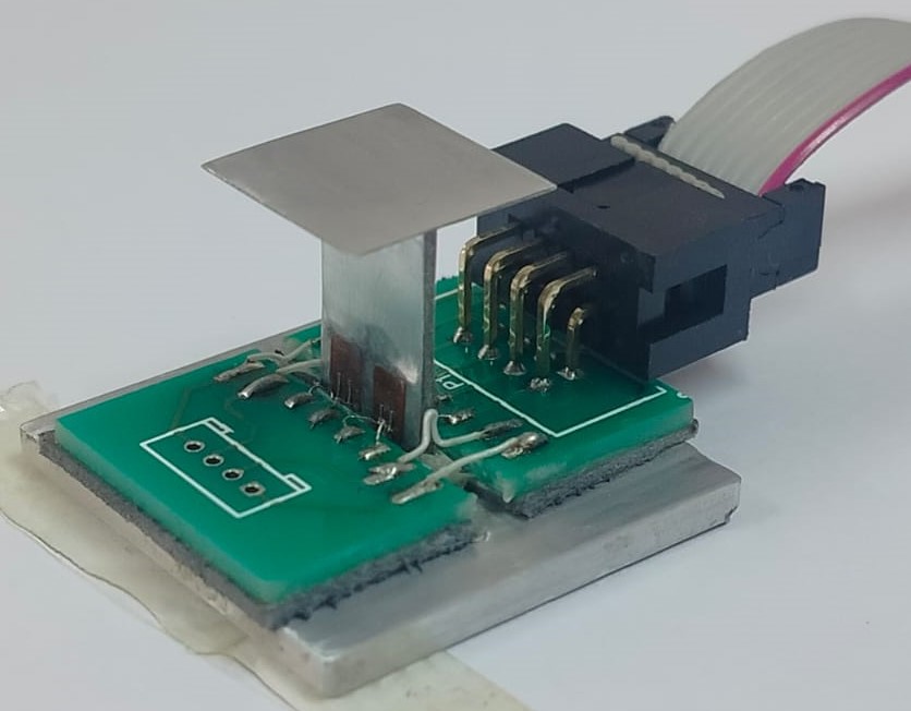
This invention tries to measure shear forces, which are oppositional forces caused by the flow of fluids over the surface of an object, in hypersonic flow environments. The primary challenge in accomplishing this is to avoid interference from pressure and acceleration loads, which current sensors struggle with. This invention achieves this to a unique degree through its innovative mechanical and electrical configuration. At the same time the mechanical system is reasonably simple, and the links between the subsystems are uncomplicated and non-mechanistic, allowing for easy accommodation for improvements and intermediate subsystems.
- Basic Design: The measurement unit consists of a cantilever beam to which a floating head is attached. When the floating head is exposed to shear, the beam bends, and the corresponding strain is measured by strain gauges that the beam is instrumented with.
- Avoiding Interference from acceleration loads:The system comprises a measurement unit placed in a first hollow portion of the object and an acceleration unit, unexposed to the flow, placed in a second hollow portion of the object. This allows for the measurement of shear forces uninfluenced by acceleration loads by calculating the difference between the readings of the two.
- Avoiding Interference from normal pressure loads: The normal pressure and temperature loads on the measurement unit are canceled out due to the electronic configuration of the strain gauges, which means that the measurement unit remains insensitive to normal-pressure, temperature and moment loads.
- Protection from High Temperature Flow: The strain gauges are attached near the base of the cantilever beam used for strain measurement to protect them from the high temperatures in the case of high-speed flows, allowing prolonged preservation of delicate components and accurate readings.
- Avoiding interference from moment loads: The floating head rests on a series of needle roller bearings which minimize the response to moment forces that may be created due to pressure gradients of shock waves commonly associated with high speed flows.
- Design Advantages: The simplicity and design wise independence of the components have various advantages: The simple design of the units allows to achieve high natural frequencies which are required for operation in impulse-facilities. The connections between components are not limited to being direct mechanical connections, which makes it possible to improve the individual components, as well as to introduce intermediate components that improve the functioning of the device.
A fully developed device directly deployable for the intended applications has been created, capable of measuring viscous forces between 0.08 and 10N, with a minimum measuring time of 1.7 milliseconds. The maximum test duration is 5-7 milliseconds.
The system has been fully developed and is ready for deployment for short duration measurements (TRL 9)
NIL
Defence, Aerospace and high-speed vehicles.
This sensor can be installed inside airplane wings/hollow buff bodies in wind tunnels for viscous drag measurement on the wing/body. Thus, it will be of interest to flow sensor developers, wind tunnel manufacturers, hypersonic flow analysts etc.
202123048366
465961

