Advanced Mechanical Testing Facility (AMTF)
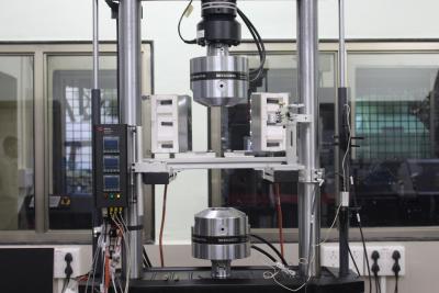
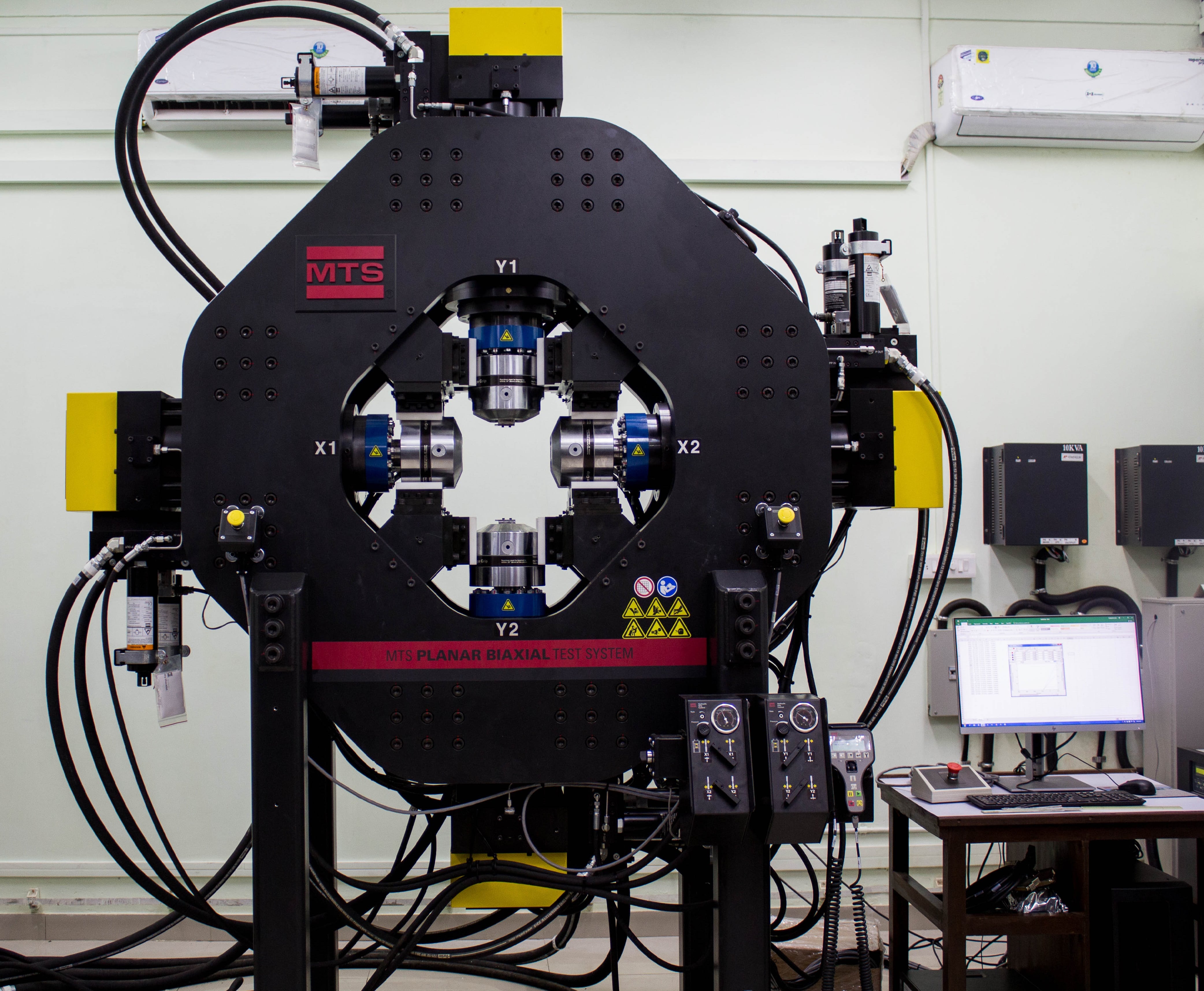
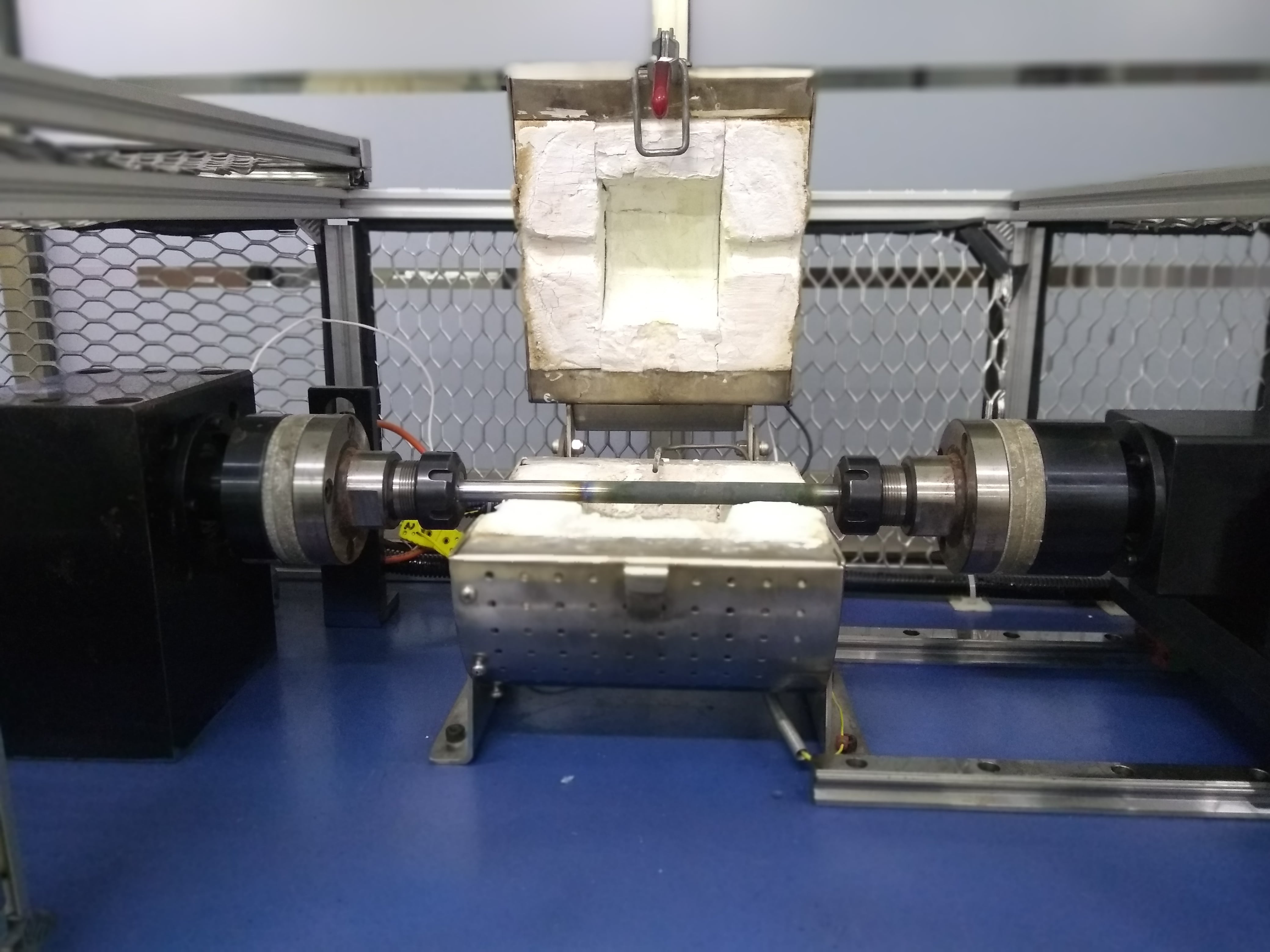
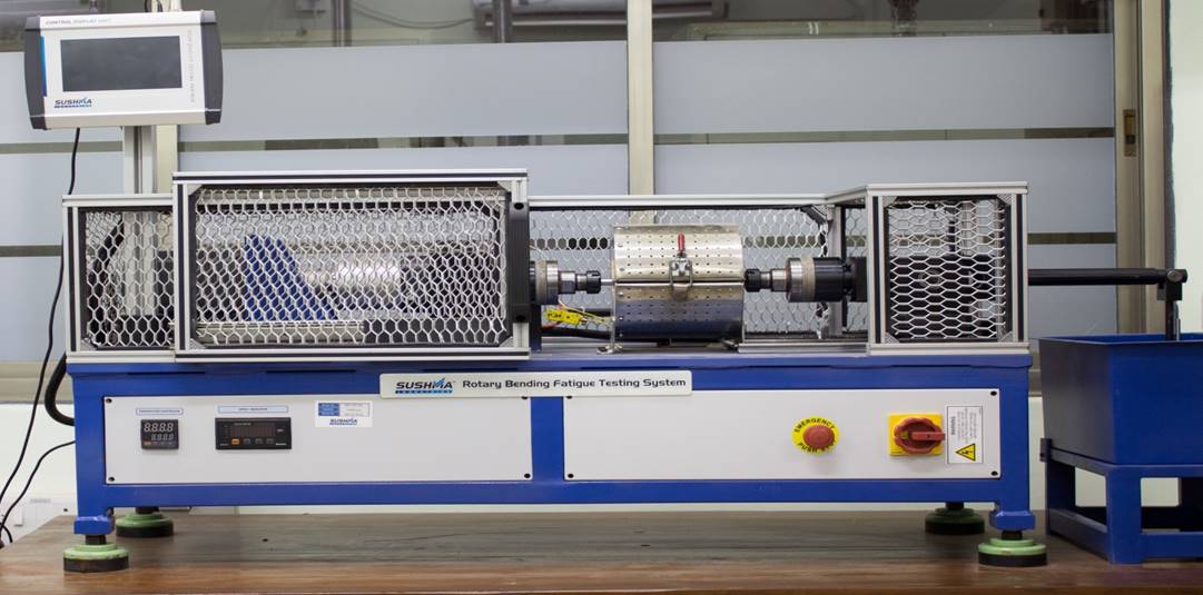
Advanced Mechanical Testing Facilities (AMTF) consists of following facility Planar Biaxial System – 100kN: This system employs multiaxial loading technology to apply and measure in-plane stresses in both the X and Y axes .It is a Servo-hydraulic testing machine with 4 actuators each having a capacity of 100 kN. All the actuators can be controlled independently. We can apply monotonic as well as fatigue loading in both x and y directions simultaneously. a) Axial Torsion Test System-250kN/2000Nm b) Axial Fatigue System- 100kN c) Rotary Bending Fatigue System- 20 Nm d) Digital Image Correlation (DIC) 2. Axial Torsion Test System-250kN/2000Nm: Axial/torsional testing simulates the multiaxial stress states of real-world operating conditions more accurately. Axial/torsional loading of tubular specimens offers a proven, highly valuable method for investigating material response to multiaxial static and fatigue stresses. Specimens are typically thin-walled tubes, and the stress states in the tube walls are mathematically well-known. Tests involve simultaneous application of torque and axial loading with some prescribed phase relationship. 3. Axial Fatigue System- 100kN: It is a versatile, high-performance servo hydraulic system for static and dynamic materials and component testing. It is proven MTS application software and has a complete selection of accessories to provide highly accurate and repeatable static and dynamic testing across the material testing continuum. 4. Rotary Bending Fatigue System- 20Nm: It is used to determine the bending fatigue property of round specimens under rotating load. During determination of the bending fatigue strength the specimen is subjected exclusively to alternating loading in order to obtain a mean value between zero positive and negative loads of equal magnitude. The rotating bar bending fatigue test can also be performed with an optionally available high temperature furnace at elevated temperatures up to 10000C. 5. Digital Image Correlation (DIC): DIC is a non-contact optical technique to measure strain, deformation and vibration which uses image processing to map the values across the whole specimen. It gives deformation values of in-plane as well as out-of-plane dimensions.
1. Planar Biaxial System – 100kN: MTS Systems Corporation, Planar Biaxial Test System 2. Axial Torsion Test System-250kN/2000Nm: MTS Systems Corporation, 809 Axial Torsion test system 3. Axial Fatigue System- 100kN: MTS Systems Corporation, Landmark 100 kN Servo Hydraulic system. 4. Rotary Bending Fatigue System- 20Nm: M/s. Sushma Industries, Rotary bending fatigue system 5. Digital Image Correlation (DIC): Correlated Solutions Image Capture: VIC-SNAP Image Processing: VIC-2D and VIC-3D
1. Planar Biaxial System – 100kN: Load capacity: Dynamic and static +/- 100kN It can be integrated with DIC (Digital Image Correlation) techniques for stain measurements. Strain data can be extracted from both the axes simultaneously using Multi-axis Extensometer. Tests can be performed with Force, displacement and strain control mode. 2. Axial Torsion Test System-250kN/2000Nm: Load capacity: Dynamic and static +/- 250 kN Torque capacity : 2000 Nm Experiments can be performed at elevated as well as and sub-zero temperatures. It can be integrated with DIC (Digital Image Correlation) techniques for stain measurements. For accurate measurements of Young’s modulus (E) and average strain values, extensometer and Clip on gauge can be used. Tests can be performed with Force, displacement and strain, Torque and angular control mode. 3. Axial Fatigue System- 100kN: Load capacity: Dynamic and static +/- 100kN Experiments can be performed at elevated as well as sub-zero temperature. It can be integrated with DIC (Digital Image Correlation) techniques for stain measurements. For accurate measurements of Young’s modulus (E) and average strain values, extensometer and Clip on gauge can be used. 4. Rotary Bending Fatigue System- 20Nm: Specifications: Machine capacity: up to 20 Nm (Bending moment) Operating speed: 200-10000 RPM Speed resolution: 1 RPM Operating temperature: ambient to 10000C @ 5000C test can conduct up to 10 Hrs. @ 7500C test can conduct up to 4 Hrs. @ 10000C test can conduct up to 2 Hrs. Temperature control: +/- 20C Component diameter: 2-16 mm Dead weight: 1N-3Nos., 2N-1No., 5N-1No., 10N-2Nos., 20N-1No., 50N-1No. Measured parameters: Temperature and rotational speed Test conduct: At constant speed and no-load At constant speed and with load At variable speed and variable load Features: · Variable adjustable bending moment by weight · Constant bending moment over the specimen length. · Adjustable rotating speed. · Self-centring specimen clamping, high alignment accuracy. 5. Digital Image Correlation (DIC): Gives strain and displacement data at each and every point in the selected area of interest. Four different pairs of lenses ranging from 25 mm to 100 mm focal length. Can be coupled with any of our mechanical testing machine to import its load cell and/or extensometer data.
Planar Biaxial System – 100kN: 1.a) Aerospace and Power Generation: To study engine turbine materials, like metal alloys, ceramics and composites, to allow them to operate at increasingly higher temperatures for improved efficiency 1.b) Ground Vehicle: To validate new material models for sheet metal or composite components that are being used to meet more stringent fuel economy targets and increased safety requirements 1.c) Construction: To study advanced materials that are increasingly used to allow more complex designs, to address security issues from natural and man-made disasters and to meet environmental requirements. 1.d) Oil and Gas Pipeline Components: To evaluate the material properties for high temperature and corrosive environment. To design high efficiency turbine, pressure vessels, heat-exchanges etc. 1.e) Large Scale Wind Turbine Structures: Efficient design of wind turbine structures by evaluating the material properties at multiaxial loading. Axial Torsion Test System-250kN/2000Nm: Axial-torsion testing machines help characterize biaxial mechanical properties of materials, both in static and dynamic conditions, which helps in choosing the right materials for different applications where components are exposed to axial torsion loading profiles. 2.a Fatigue Testing This system is ideal for the exacting demands of material fatigue testing. Highly stiff integrated actuator beams, patented hydraulic grips, high resolution force transducers and precision alignment fixtures combine to deliver tightly controlled and consistent through-zero specimen loading. Example: Constant Amplitude, Variable Amplitude, Low Cycle Fatigue (LCF) and High Cycle Fatigue (HCF) 2.b Fracture Testing The system can be readily configured to perform linear elastic and elastic-plastic fracture toughness testing. The system load frame can be used for both pre-cracking and fracture testing and equipped with a selection of standard compliant grips and precision clip-on displacement gauges. Example: Fracture Toughness, Fatigue Crack Growth, Crack Propagation, JIc and KIc 2.c Component Testing Highly configurable MTS Axial Torsional System feature the test space and performance flexibility required to perform both static and dynamic component testing. These systems can be equipped with fixtures for single and multiple specimens, as well as a full selection of extensometers that are versatile enough to measure displacement from a variety of locations on a specimen. Example: Strength and Mechanical Properties of Components and Assemblies 2.d Monotonic Testing Multipurpose MTS Axial Torsion systems are equipped to meet a full spectrum of monotonic—or static-material testing requirements. These systems run industry-leading MTS Test Suite software, which combines powerful test definition capabilities with simplified runtime operation and the ability to analyse data report test results in a variety of standard and custom formats. Example: Tensile, Compression, Bend and Stress Relaxation Axial Fatigue System- 100kN: 3.a Fatigue Testing The MTS Landmark system is ideal for the exacting demands of material fatigue testing. Highly stiff integrated actuator beams, patented hydraulic grips, high resolution force transducers and precision alignment fixtures combine to deliver tightly controlled and consistent through-zero specimen loading. Example: Constant Amplitude, Variable Amplitude, Low Cycle Fatigue (LCF) and High Cycle Fatigue (HCF) 3.b Fracture Testing The system can be readily configured to perform linear elastic and elastic-plastic fracture toughness testing. The system load frame can be used for both pre-cracking and fracture testing and is equipped with a selection of standard compliant grips and precision clip-on displacement gauges. Example: Fracture Toughness, Fatigue Crack Growth, Crack Propagation, JIc and KIc 3.c Component Testing Highly configurable MTS Landmark systems feature the test space and performance flexibility required to perform both static and dynamic component testing. These systems can be equipped with fixtures for single and multiple specimens, as well as a full selection of extensometers that are versatile enough to measure displacement from a variety of locations on a specimen. Example: Strength and Mechanical Properties of Components and Assemblies 3.d Monotonic Testing Multipurpose MTS Landmark systems are equipped to meet a full spectrum of monotonic—or static-material testing requirements. These systems run industry-leading MTS Test Suite software, which combines powerful test definition capabilities with simplified runtime operation and the ability to analyse data report test results in a variety of standard and custom formats. Example: Tensile, Compression, Bend and Stress Relaxation Digital Image Correlation (DIC): Strain Contour on the specimen, strain on individual points, average and maximum strains and various other geometric data can be obtained by using DIC technique. Using the High Speed Camera, crack propagation can be clearly studied. Can use DIC to analyse images of in situ tensile or compression test.
Ground Floor:23, Mechanical Engg, Dept.
Contact No: 022-2159-3703
- K T Benny