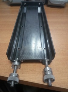
A composite mounting tray comprises a rectangular bottom base wherein two length side and one breadth side are vertically bent at 90 degree and at least two parallel slots at the bottom base that extend along the length of the bottom base. The composite tray is manufactured in multifold layers.
The existing practice relies on Aluminium alloy sheet and stainless steel for manufacturing avionics mounting trays, which requires forming, punching, drilling, and riveting. This leads to increased assembly time, weight, and stress concentration at joints and holes. Such trays are also prone to humidity, dust, salt, and fungus accumulation. They must meet MIL standards for shock, vibration, and environmental resistance. Current designs lack localized thickness variation and multifold layups needed for high rigidity. Therefore, there is a need for a lightweight, single-piece composite mounting tray that reduces manufacturing time and cost, while withstanding harsh conditions and dynamic loading.
- Single-Piece Composite Structure: The mounting tray is made as a single-piece structure using high-strength composite materials like CFRP, GFRP, and Kevlar, which reduces manufacturing time, cost, and eliminates stress concentrations caused by joints and fasteners.
- Enhanced Rigidity Through Layup Design: A multifold layup with localized thickness variations and inclined stiffening walls provides enhanced flexural and torsional rigidity, enabling the tray to withstand multiple high shock loads (50g vertical and 22g lateral).
- Optimized Slot Geometry: The tray’s rectangular base includes two parallel slots with vertical closures and wider areas at the front, designed to reduce pin bending and distribute load effectively, improving mechanical strength and shock resistance.
- Fastener-Free Assembly Advantages: Absence of rivets and fasteners minimizes surfaces prone to fretting and environmental damage, while wider slots offer greater contact area and traction for LRUs, allowing easy fitting even if LRU rails are bent or misaligned.
- Stress Reduction and Smooth Operation: Progressive thickness variation and inclined walls at slot ends prevent stress concentration, avoid direct impact with the tray’s back face, and facilitate smooth loading and unloading of LRUs without buckling rails.
- Optional Customization Features: Optional features include integrating metal mesh for electrical and thermal conductivity, lightning protection, special coatings to reduce wear and friction, and hybrid composites for customizable mechanical and thermal properties.
The present invention describes a composite mounting tray comprising a rectangular bottom base wherein two length sides and one breadth side are vertically bent at 90-degree, at least two parallel slots at the bottom base along the length. The slots contain-plurality of holes which are used for fixing the tray to aircraft-frame. The rectangular bottom base is extended to the length of the tray comprising a wilder area at front and a flat portion at the end. The slots have vertical closure connected to the flat portion with vertically inclined wall. The progressive thickness variation at the back and side walls of the tray gives it the flexural and torsional rigidity to withstand the bending and the out of plane stresses.
Demonstrated prototype tray with actual LRU for vertical and lateral shock tests.
5
The composite tray improves shock resistance and structural rigidity, which enhances safety and reliability of avionics systems. This contributes to safer air and sea travel, benefiting both defense personnel and civilians.
- Aerospace and Aviation industry
- Defense and Military vehicles
- Industrial equipment and electronics enclosures
- Space and Satellite systems
- Marine and Naval industry
Geography of IP
Type of IP
201721014294
545305

